 Download TSTower for Guyed Masts User's Manual
Geometry Definition
Based on the given tower height, top and bottom face widths, and number of sections, TSTower* generates the geometry of the tower, calculates the top and bottom dimensions of every section. The user later defines the number and type of panels for each section and then defines the properties and members of every panel. The geometry window is very user-friendly and enables the engineer to navigate from section to panel to member and copy properties of a section or a panel to other sections and panels. The next step, the user defines the guy system by defining the number and sizes of guy levels, guying details and torsion resistors. The user sees the geometry of the tower and guys to scale on the screen as the data being defined.
The engineer may use the Latticed Tower Geometry Screen to:
- Define the height or number of panels of sections and top and bottom widths of each section
- Define defaults for the generation or addition of new sections
- Add a section or sections at the top or bottom of a tower
- Change tower cross section from triangular to square or vice versa
- Define bracing type from one of the following, single, inverted single, x-bracing or k-bracing. A subdivision of the leg into two or four can be defined for each of these bracing types
- Select member type and size from a large database of standard members. Define grade of steel and connection details for each member for capacity calculations
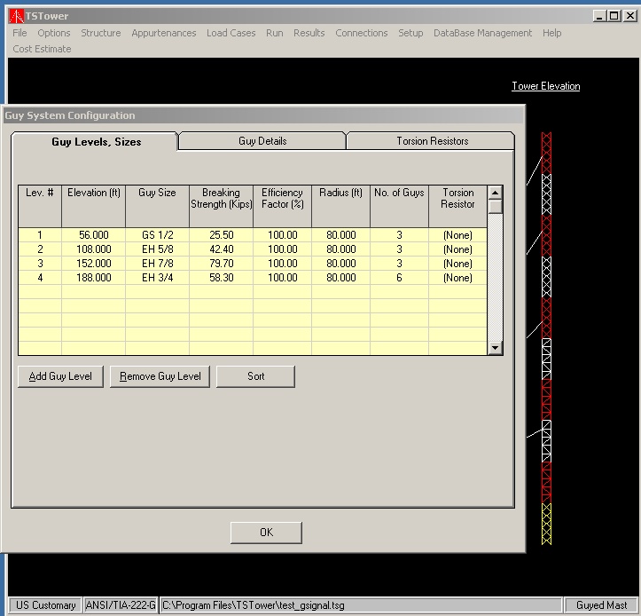
The engineer may use the Guy System Configuration Screen to:
- Define the guy size, type, height, guying radius and end efficiencies of each of the guy levels
- Define orientation, elevations and initial tensions of each of the guy wires
- Define the torsion resistors and their configurations
TSTower also has the capability of storing and retrieving complete sections from a database that is previously defined by users. This functionality saves the user the effort of having to re input the data of sections that have been defined earlier. It also enables users to save, sort and retrieve section by tower manufacturers. The guy wires are selected from a database consisting of the most commonly used structural strands.
Antennas and Ancillaries Definition
From this screen, the engineer may define the type and size of antennas used. A comprehensive database of antennas is available and comes integrated with TSTower. Also other appurtenances such as point loads, transmission lines and ladders can be defined on this screen. The exact location and orientation of the appurtenance is determined in space depending on the engineer’s definition of the radius, azimuth, and orientation.
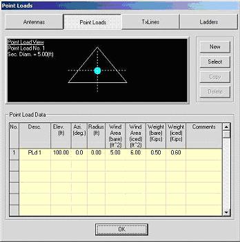
Again, TSTower draws to scale the cross-section of the tower at the specific level showing the appurtenance and its location with respect to the tower. The engineer need not to do any of the forces calculations as that is generated internally as per the specified relevant codes.
Loads Preparation and Analysis
The engineer specifies the design wind and ice requirements and the wind angles required for the analysis. TSTower calculates all the applied loads following the specified design code. A database of US counties containing the design information such as design wind speed, ice thickness, wind speed for iced conditions and frost depth is available for users to choose from.

The analysis is performed using a true 3-dimensional finite element Beam-cables model with non-linear geometrical capabilities. Analysis can be performed using the program analysis engine TSTower or utilizing other programs for the analysis as Autodesk® Robot™ which has the ability to model catenary cables accurately and quickly. In either case the program communicates seamlessly to write the input file (nodes, elements, etc.) and read the results, once the analysis is completed, for post-processing. The user can specify multiple wind directions as well as different loading case for the same analysis.
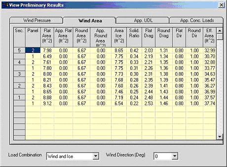
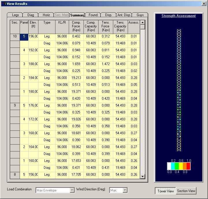
Results
Preliminary results are available for each of the wind directions of the analyzed loading combinations. From the preliminary results, the user can check the values for wind pressure, ice thickness, effective projected areas of structure, appurtenances uniformly distributed loads and concentrated loads.
The results of the structural assessment of the tower are shown for tower legs, diagonals, and horizontals using the compression diagram showing actual member forces versus capacities. Results can be viewed for shown for maximum envelope or a specific wind direction.
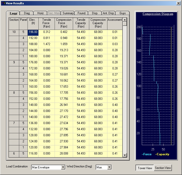
A colored contour summarizing the assessment results of all tower members including secondary members can be also reviewed from the final results screen.
Printout
TSTower calculations printout is as detailed as the engineer’s requirements. The printout may include all load calculations, applied forces, resulting deformations, stresses and member assessment. TSTower also generates a profile of the tower that can be exported in .DXF format for inclusion in the drawing. The design profile shows tower layout, design standard, wind and ice loads and antennas and lines table.
Conclusion
In conclusion, our customers have indicated that TSTower is robust software that helped them cut dramatically their engineering time. We hope that that is your conclusion too after you go through the working demo version of TSTower that we are offering free of charge. This demo version is a full working version with a height limitations only, so feel free to browse through it.
Download TSTower for Guyed Masts User's Manual
For more information do not hesitate to contact us:
Email: TSTower@Towersft.com
Phone: +1 (905) 877-8885 ext. 1216
Fax: +1 (905) 877-8835
*TSTower is a product of TowerSoft Inc.